SNU 3DP is a software to design an apparel with repetitive mesh motif using a 3D printer. You can print a whole or a partial of a garment which can be connected to fabrics with no regard to the type or the size of the 3D printer being used.
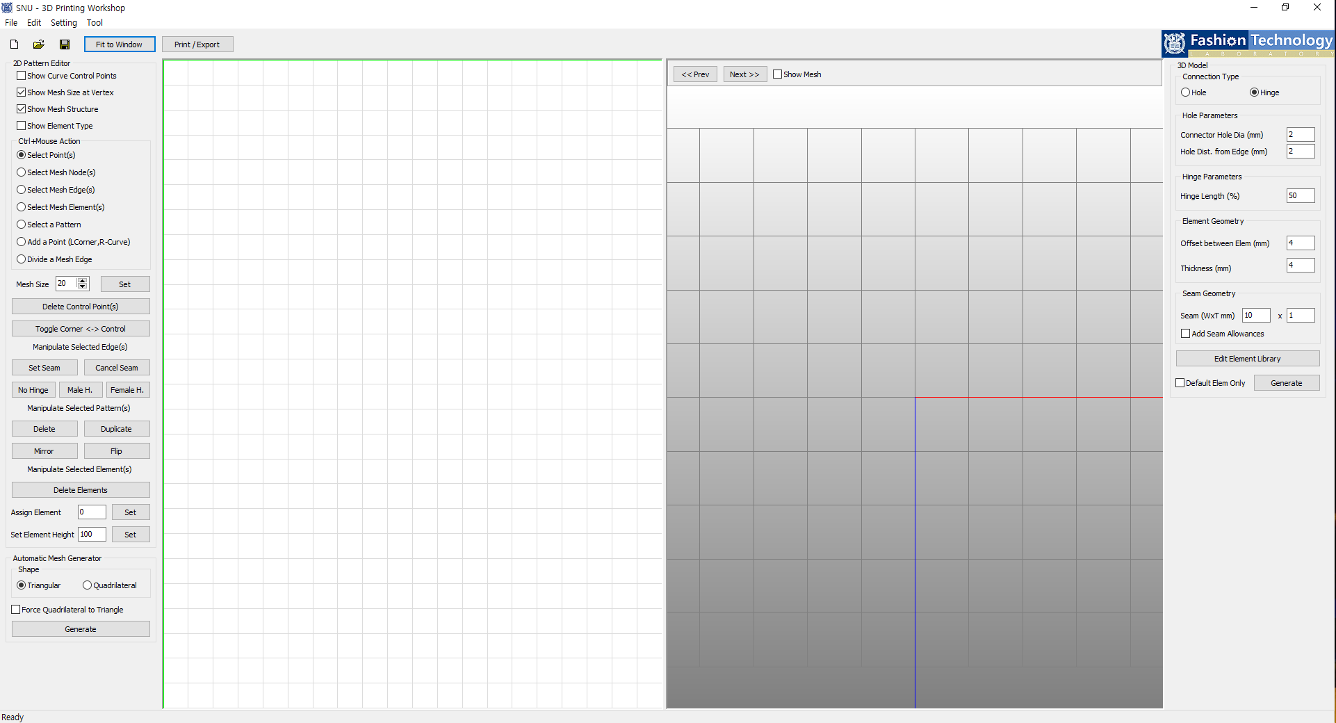
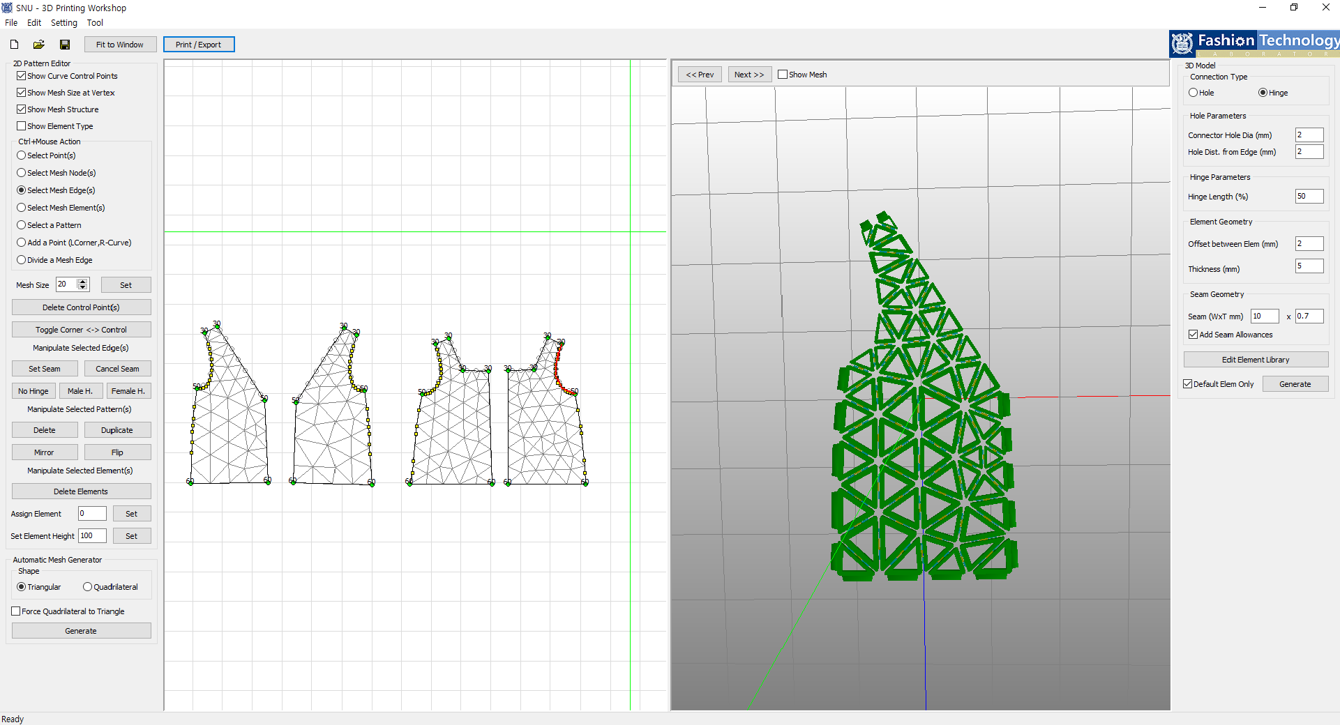
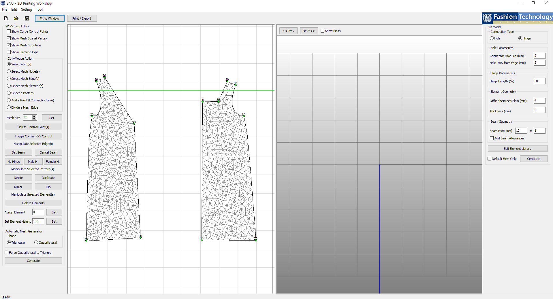
In this section, you can manage information presented on the pattern.
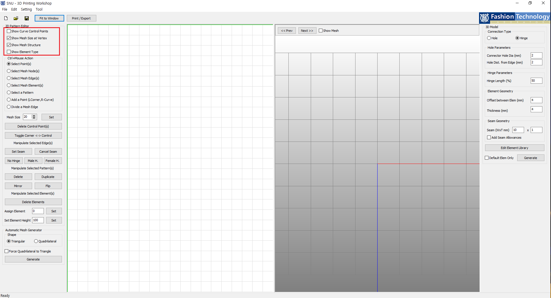
'Show Curve Control Points' shows control points of curve lines on the pattern.
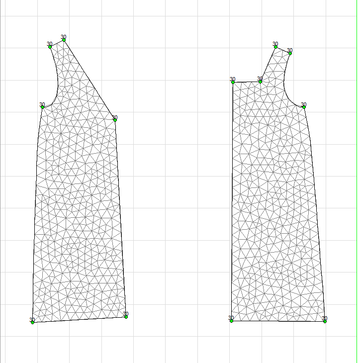
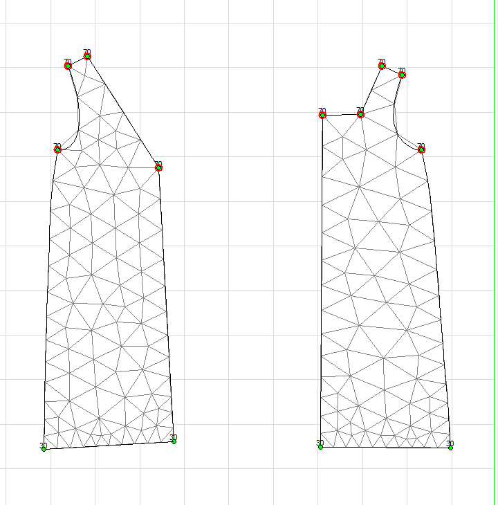
'Show Mesh Size at Vertex' shows mesh size info on patterns' corner points.
'Show Mesh Structure' presents mesh structure with the pattern.
'Show Element Type' marks used element number on each mesh.
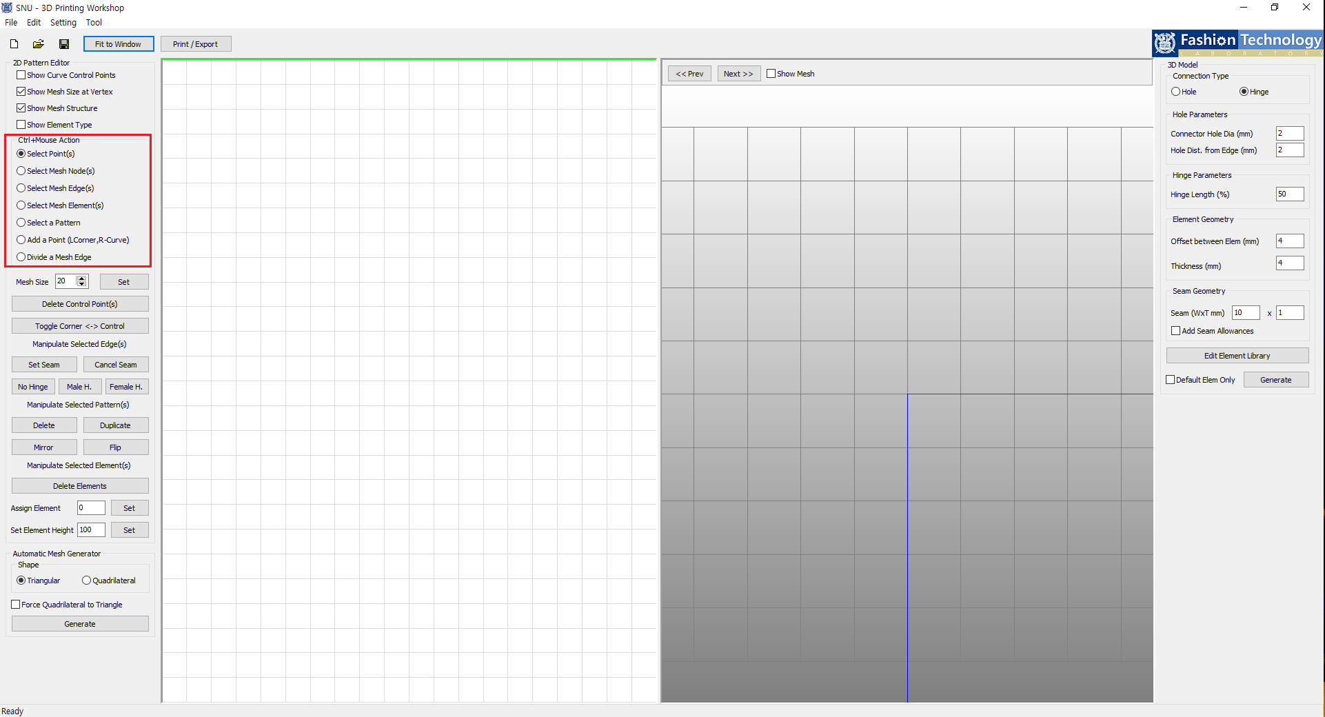
You can control basic selection action using computer mouse in this section.
All actions must be done while pressing the 'Control' key. By additionally pressing the 'Shift' key, you can select multiple features at the same time.
'Select Point(s)' selects point(s) on the outline of the pattern.
'Select Mesh Node(s)' lets you select a vertex where meshes converge. You can modify the mesh structure with this.
'Select Mesh Edge(s)' selects mesh edge.
'Select Mesh Element(s)' selects mesh(es).
'Select a Pattern' selects pattern(s).
'Add a Point (L-Corner, R-Curve)' lets you add a point on a pattern or change a straight line into a curve.
Left click (of a mouse) near the outline of a pattern adds a point which modifies the overall shape of the pattern.
Right click on the pattern edge changes a straight line into a curve.
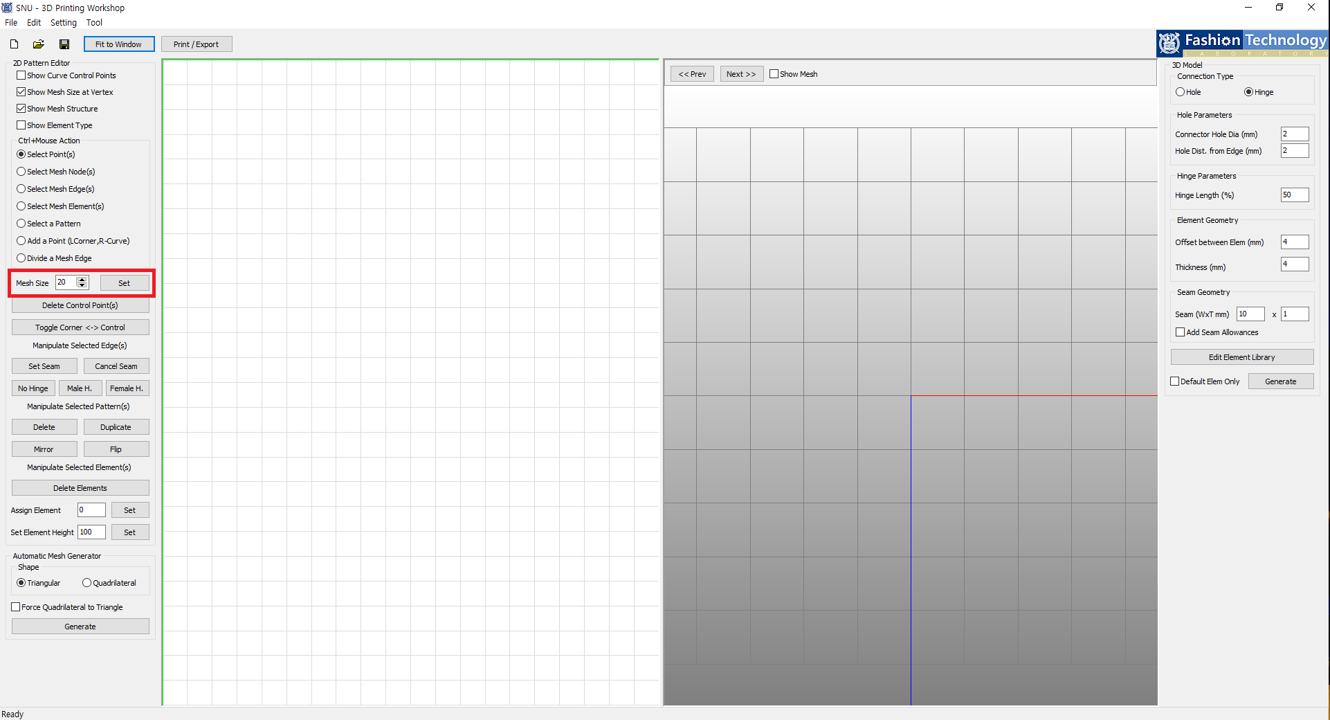
'Divide a Mesh Edge' splits mesh into smaller meshes.
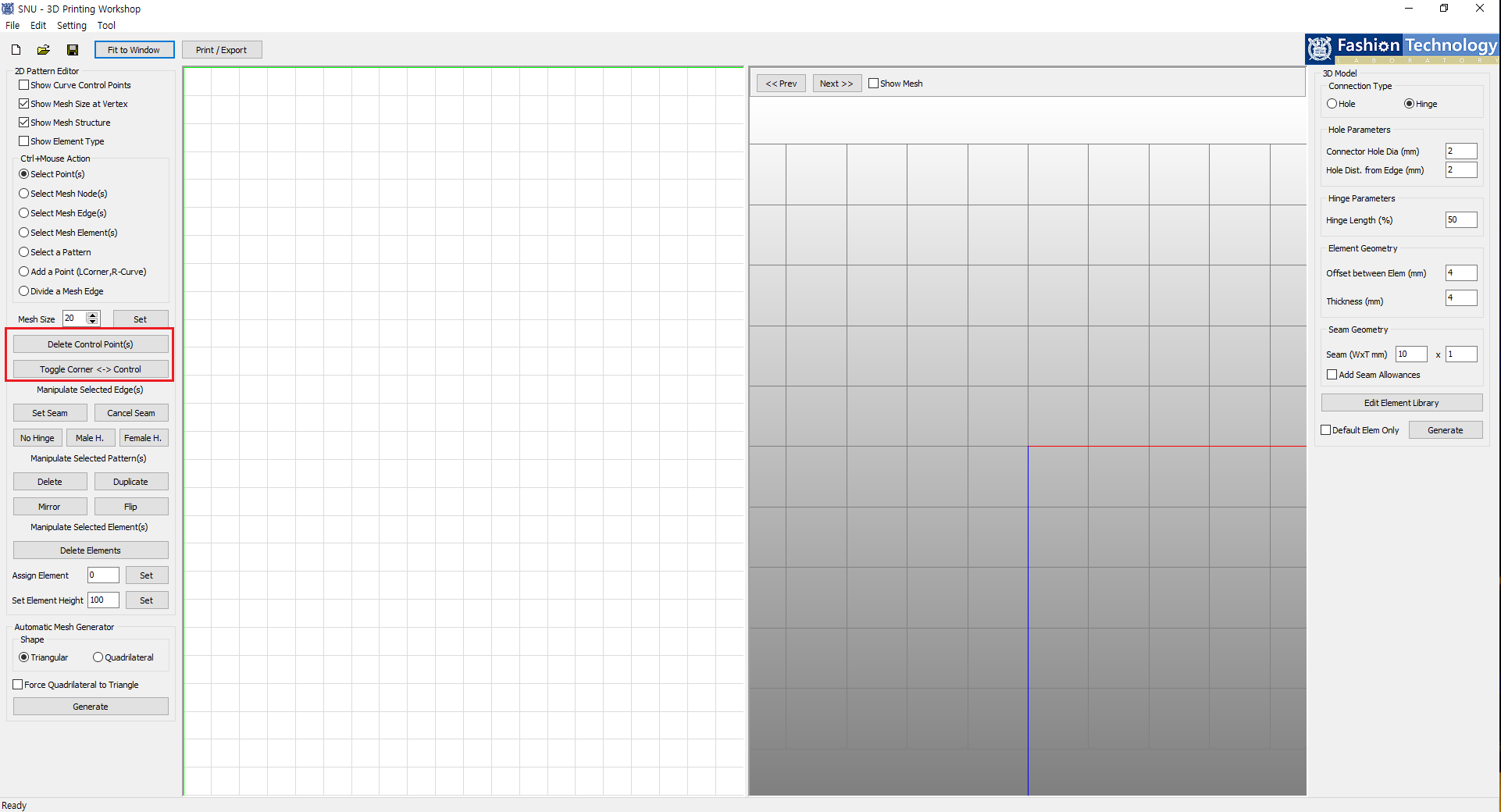
'Delete Control Point(s)' removes control point(s) on a curve which changes the curvature of the line.
'Toggle Corner <-> Control' toggles corner points and control points.
At initial start-up of the program, you must select hinges to be used.
Hinge files are stored in 'data' > 'hinge' folder and two hinges must be selected in order.
First select a hinge used to connect meshes within segment, then select a hinge used to connect segments (hinge-pin.obj).
If you don't like the selected hinge, you can design a new hinge model.
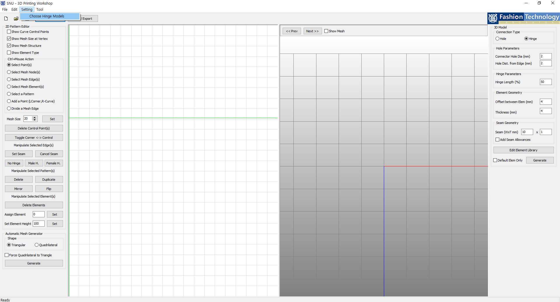
You set new hinges in 'Settings' > 'Choose Hinge Models'.
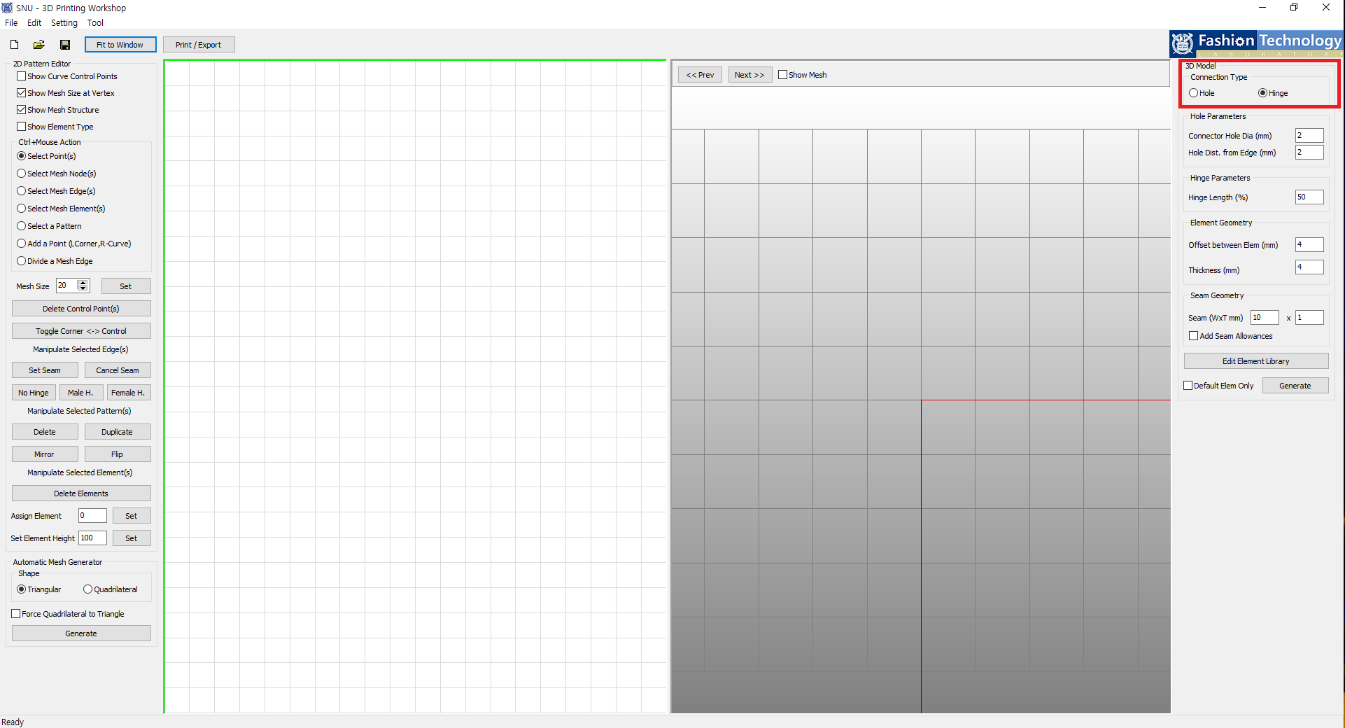
Hole type punctures holes on meshes for connection. In this case, you can connect pieces using o-rings etc. when printed.
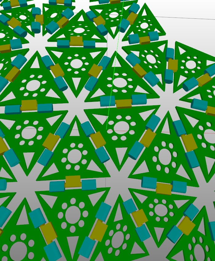
Hinge type automatically creates hinges for connection. Every meshes within a segment are connected when printed.
You can change hinge models through 'Setting' > 'Choose Hinge Models'
and selection must be held to the following order:
1. connection within a segment,
2. connection of segments.
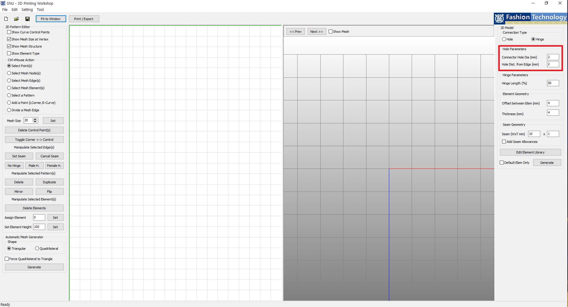
You can change a diameter of connector holes and a distance of a hole from the mesh edge.
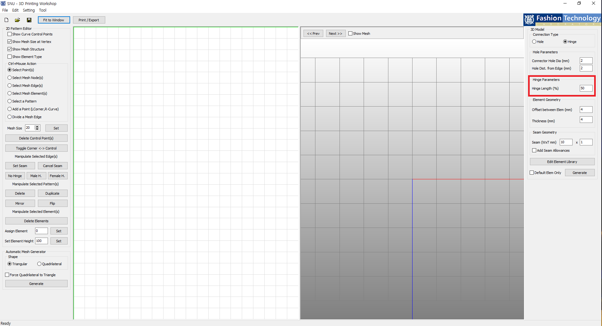
You can set the total length of a hinge in percent unit. It is recommended that you put number bigger than 15.
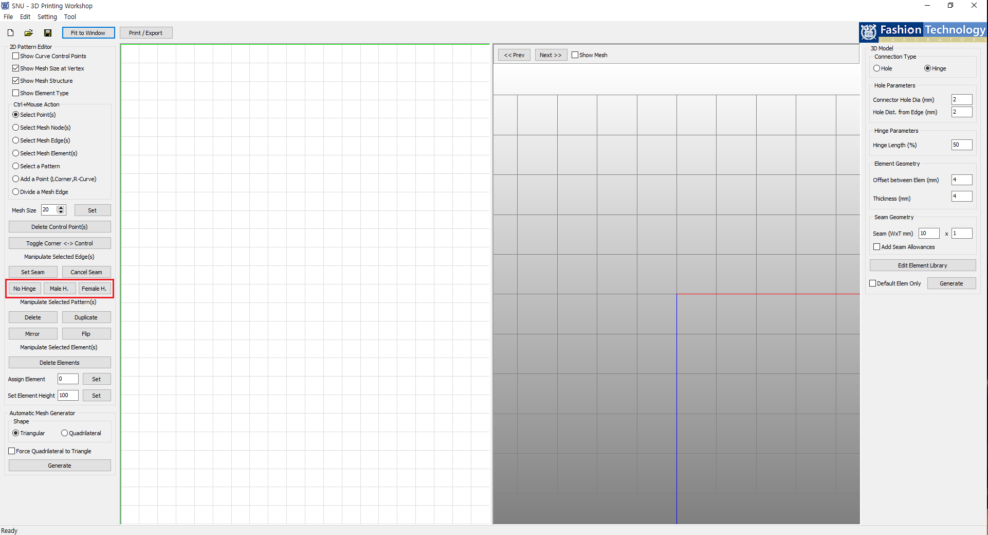
You can remove existing hinge or change its type When mesh edges are selected.
'No Hinge' removes hinge, 'Male H.' creates male type hinge and 'Female H.' creates female type hinge.
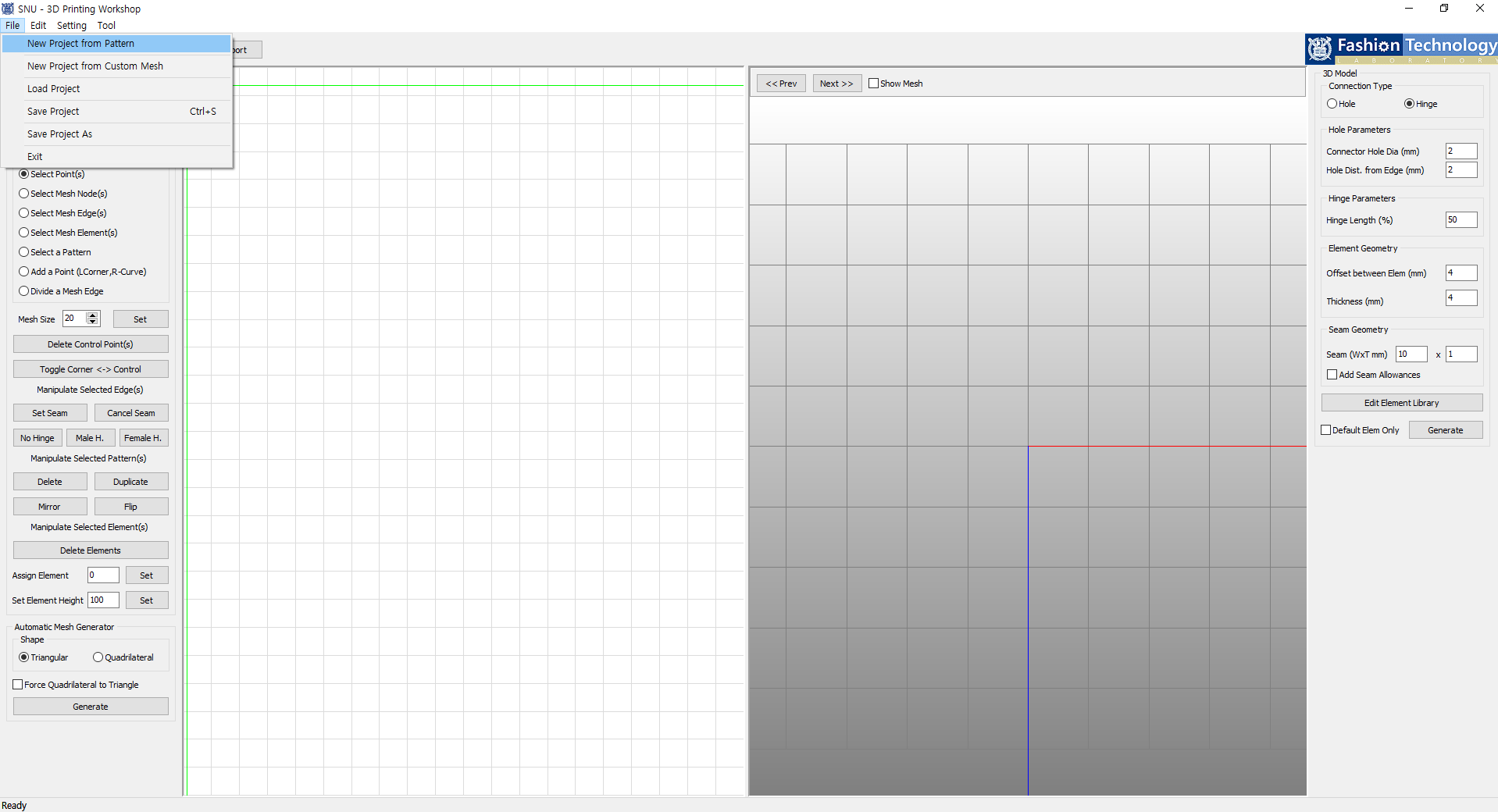
Any pattern files in .Pattern extenstion can be loaded.
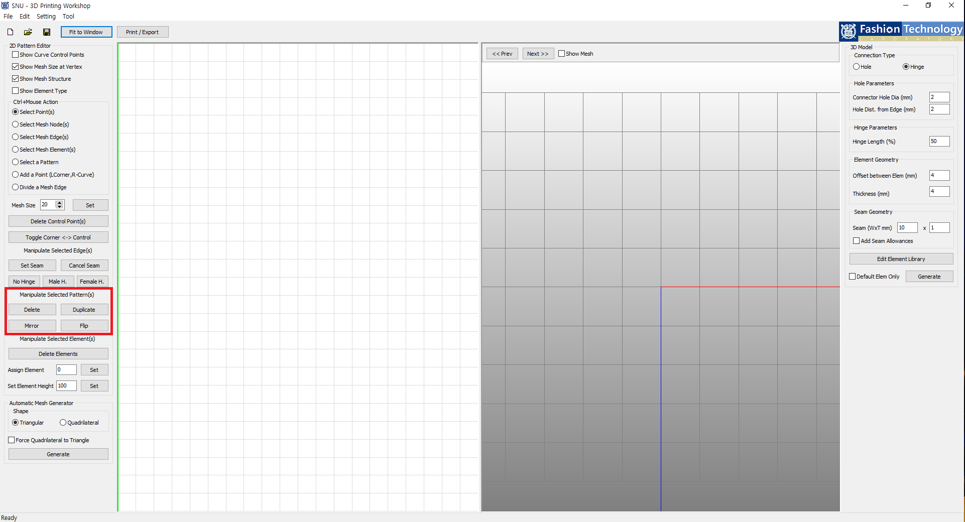
Loaded patterns can be deleted, duplicated, mirrored and flipped when selected.
You can also move or add points to the pattern using 'Select Point(s)' or 'Add a Point'.
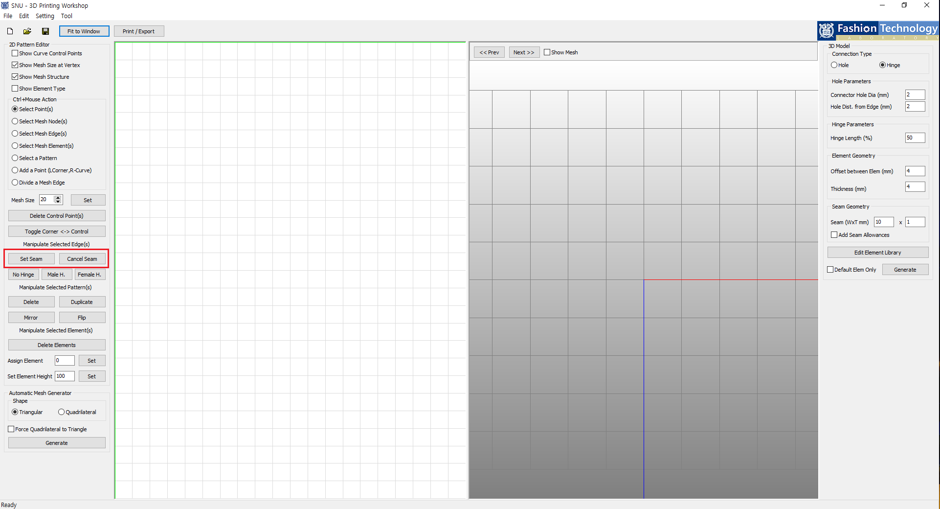
You can add or remove seam with 'Set Seam' and 'Cancel Seam' when mesh edges are selected.
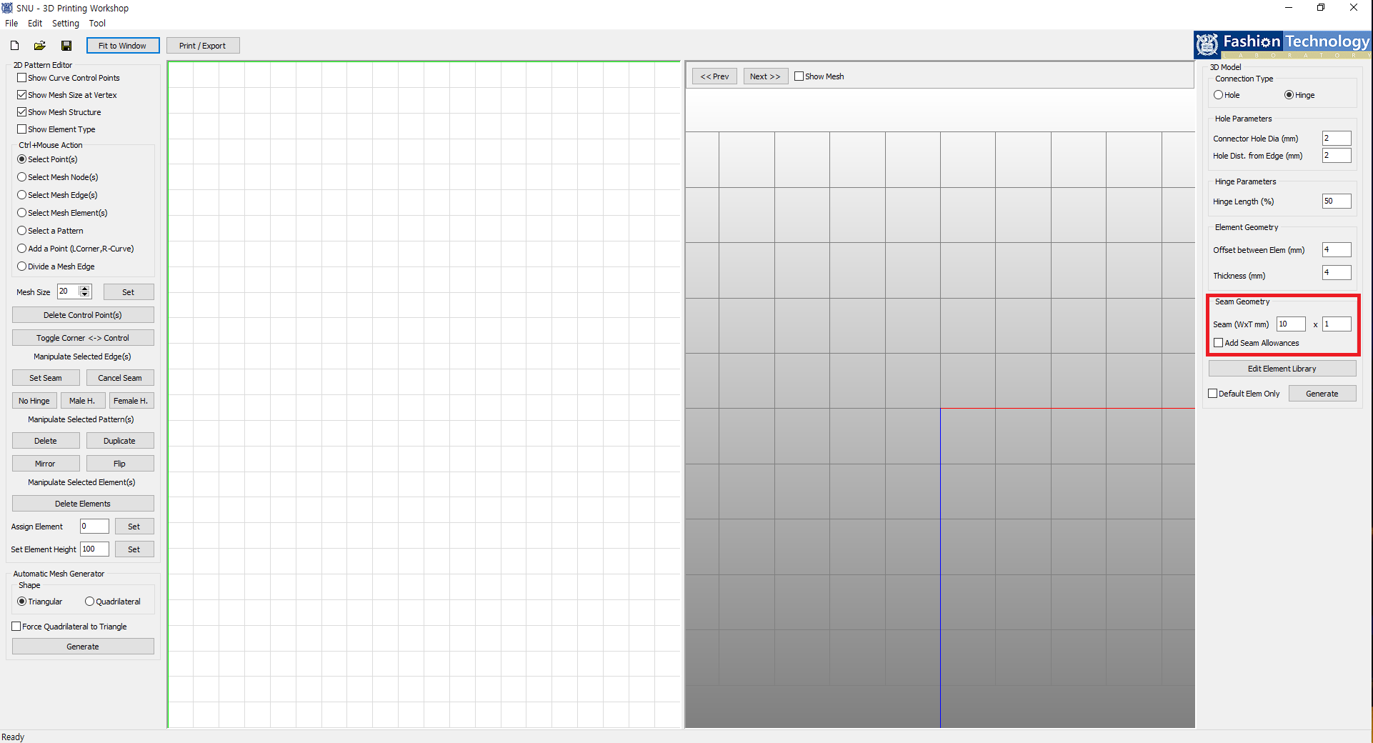
Here you can set width and thickness of the generated seam.
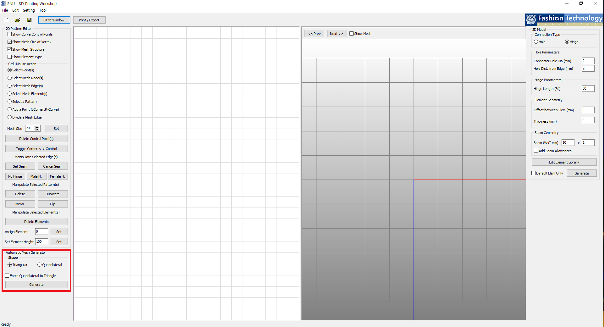
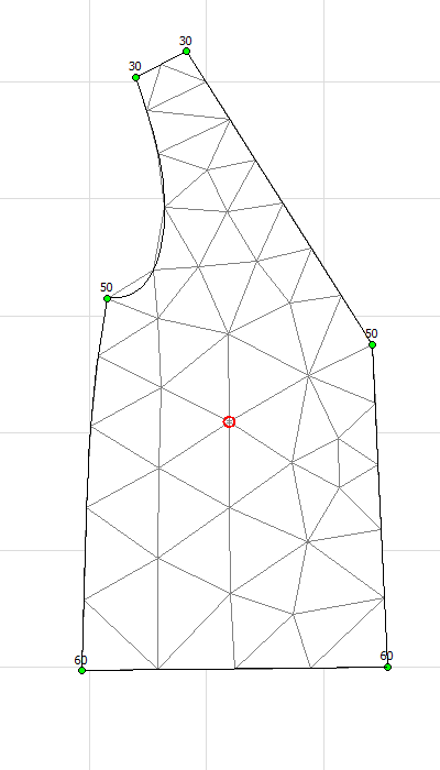
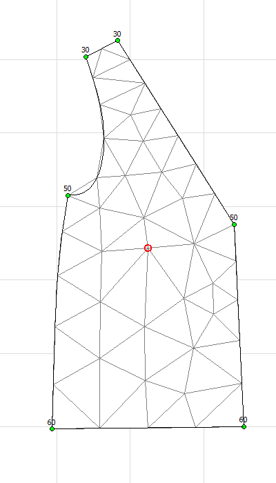
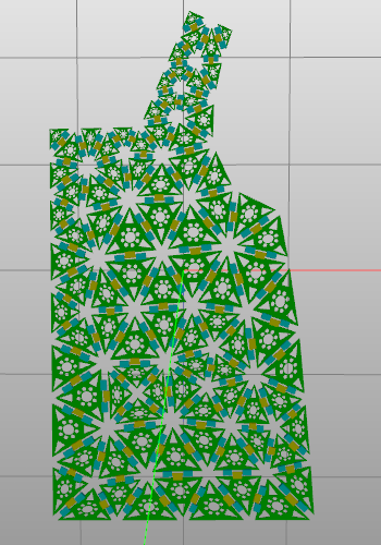
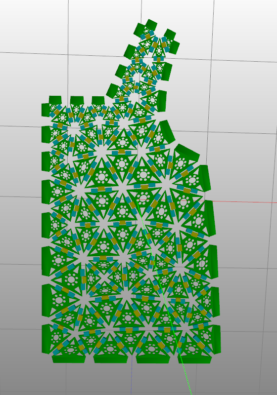
Tri-mesh and quad-mesh are available and you can check out the result by clicking 'Generate' button.
'Force Quadrilateral to Triangle' converts quad-mesh to tri-mesh.
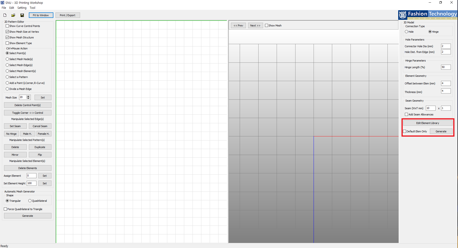
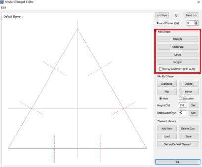
'Edit Element Library' pops a new dialog window to design elements as below.
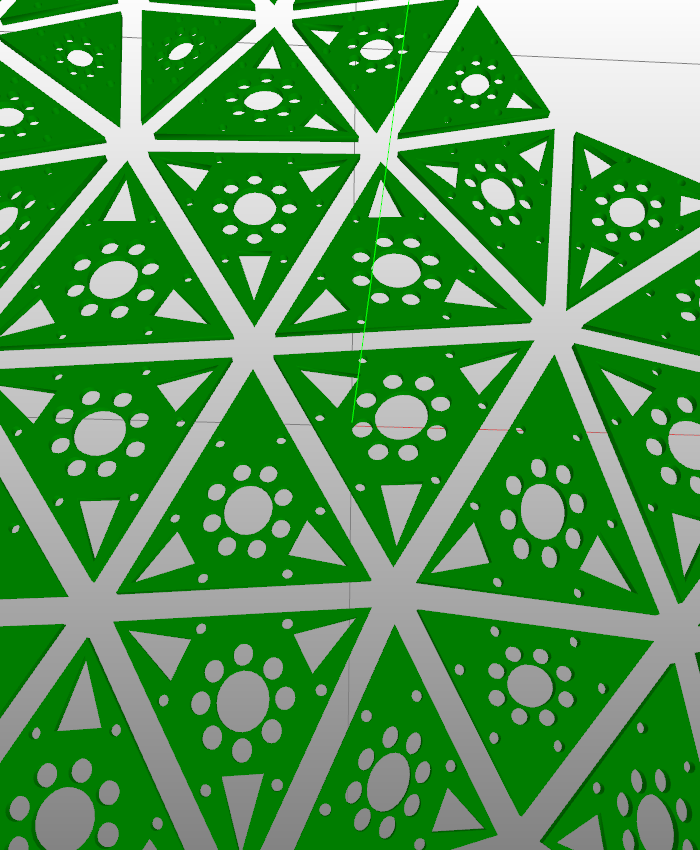
When 'Default Elem Only' is checked, a model with only default element design is generated.
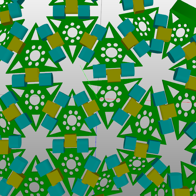
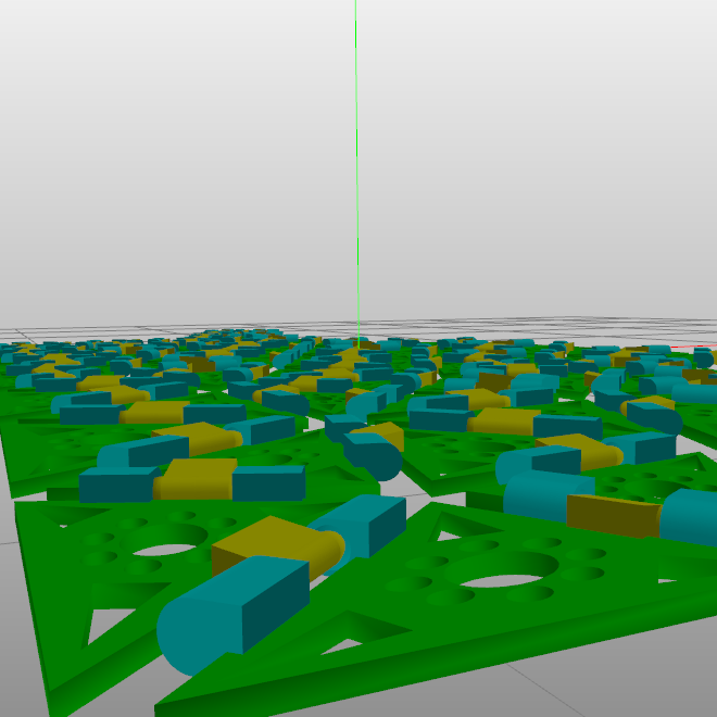
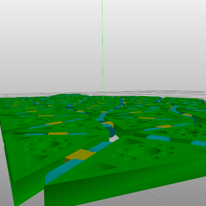
When done, you can check out your apparel model with 'Generate' button.
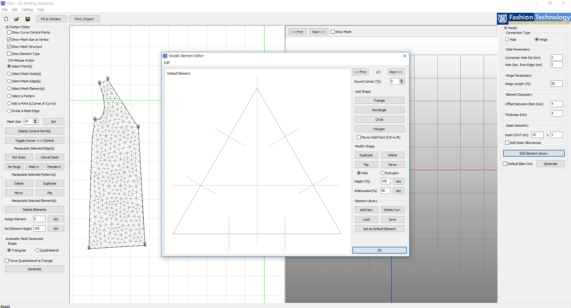
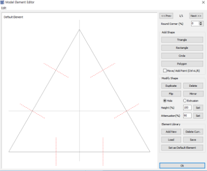
This is where you design elements.
Red dotted lines shows where holes will be punctured when connection type is set to hole.
Error will occur when design features overlap.
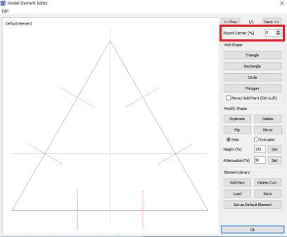
'Round Corner' rounds off corners.
It is recommended to put number smaller than 5.
Here you can add primitives used in element design.
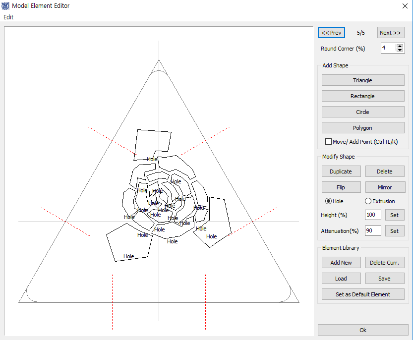
You can move or add a corner points when 'Move/Add Point' is checked.
Point movement can be done with the left button and addition can be done with the right button of the mouse.
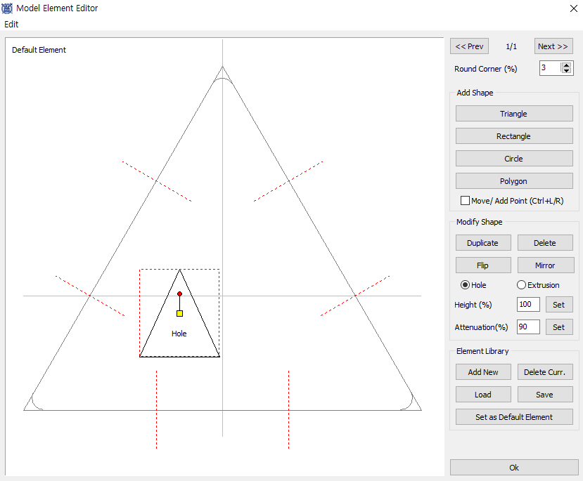
I have created a triangle here to show how you can modify figures.
Relocation of a figure is possible with mouse left button while pressing the 'Control' key and the cursor on the yellow square in the middle of the figure.
Sizing is possible with mouse right button, cursor dragged from the identical yellow square while pressing the 'Control' key.
Rotation is possible with the 'Control' key and the cursor dragged from the red dot at the top of the figure.
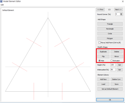
Here you can duplicate, delete, flip or mirror the designed figure.
'Hole' punctures and 'Extrusion' extrudes the figure.
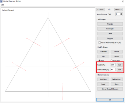
These are availabe settings for 'Extrusion'.
'Height' sets the height of the extrusion.
'Attenuation' sets the extrusion shape from pillar(when 0) to pyramidial(when 100) by its value.
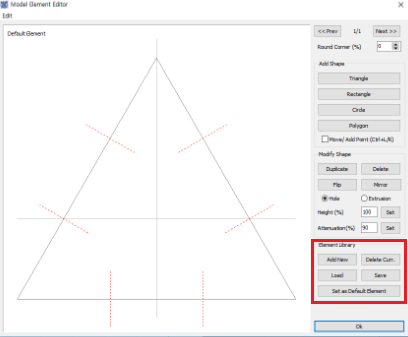
In this part you can add new element design or delete current design.
You are abole to move around the designs with 'Prev' and 'Next' button.
You can open stored design through 'Load' and save new design through 'Save'.
When 'Set as Default Element' is checked, the current element design is set as a default.
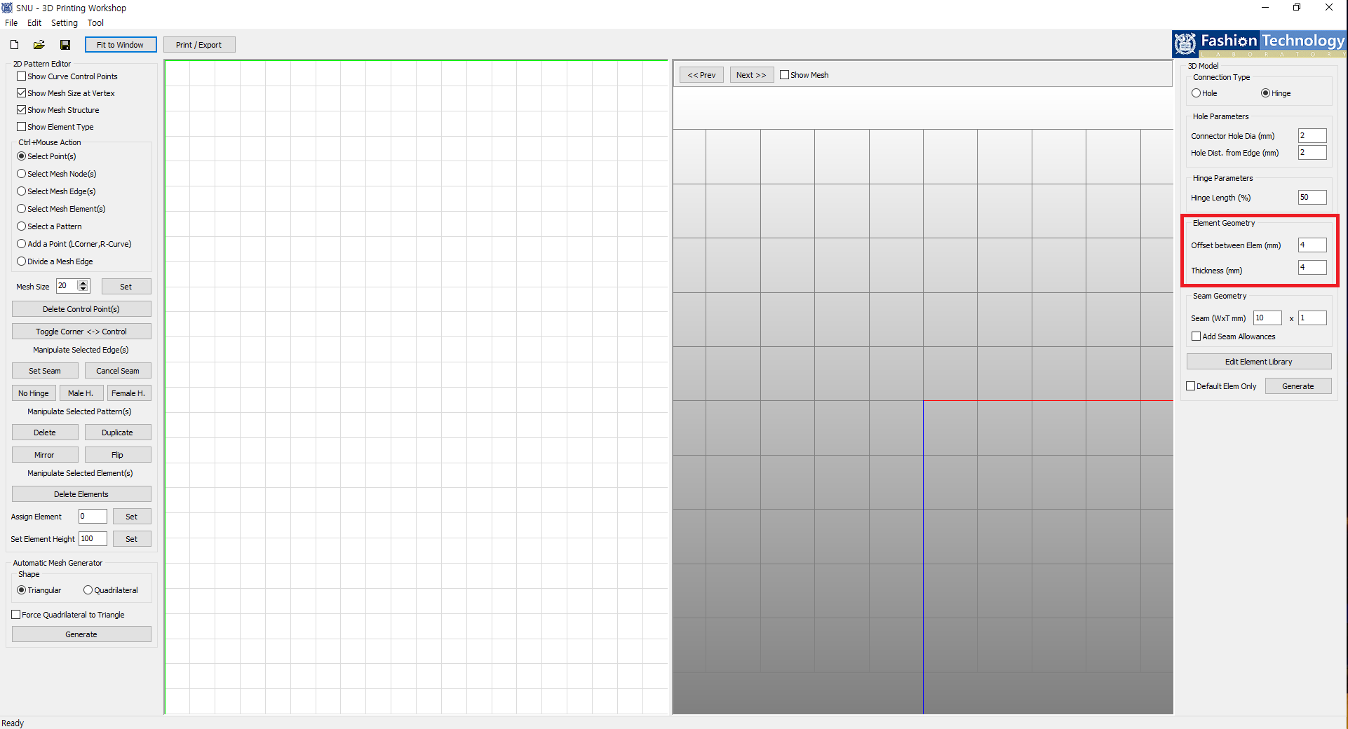
In 'Offset between Elem (mm)' you can set distance between elements(meshes).
'Thickness (mm)' literally sets the mesh thickness.
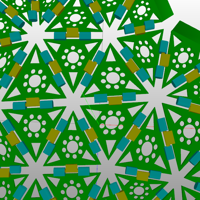
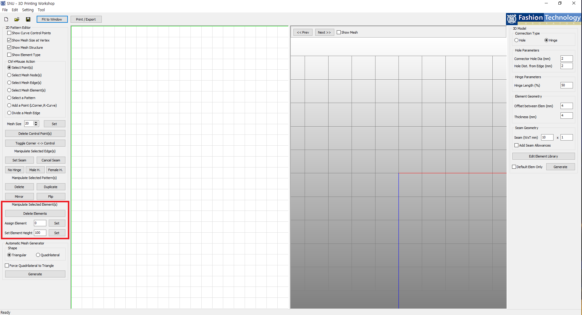
Here you can modify selected elements.
'Delete Elements' removes selected elements. You'll be able to check the removal in 3D model.
If multiple element designs exist, you can set specific design to each mesh through 'Assign Element' button.
'Set Element Height' sets absolute height of the elements only when they are extruded figure.